Choosing the right Xlpe Cable is not a simple matter of selecting the thickest conductor. The decision affects safety, heat control, installation cost, service life, and future maintenance. A cable placed in a dry underground duct faces different stresses from one installed beside hot equipment or exposed to moisture. Small details matter.
Dr. M. S. Naidu, a respected high-voltage engineering author, is often associated with a practical principle: “Cable selection is a system decision, not a catalogue decision.” That idea remains useful. Voltage rating, conductor material, insulation thickness, screen design, sheath protection, and short-circuit performance must work together. A 6.6 kV cable, for example, should not be judged by voltage alone. Soil temperature, grouping, burial depth, load diversity, and allowable voltage drop can change the correct choice.
This guide examines the main XLPE cable types, including single-core, multicore, armoured, unarmoured, copper, and aluminium designs. It also explains where each type performs best. Some choices appear economical at purchase but create difficult joints, larger bending spaces, or higher losses later. That risk is easy to underestimate. It is worth checking the installation drawings twice.
There is no universal “best” Xlpe Cable. The best option depends on the network, environment, accessories, and maintenance strategy. Engineers should verify calculations against applicable standards, manufacturer data, and actual site conditions. Even experienced teams can miss one variable. Careful comparison reduces that possibility.
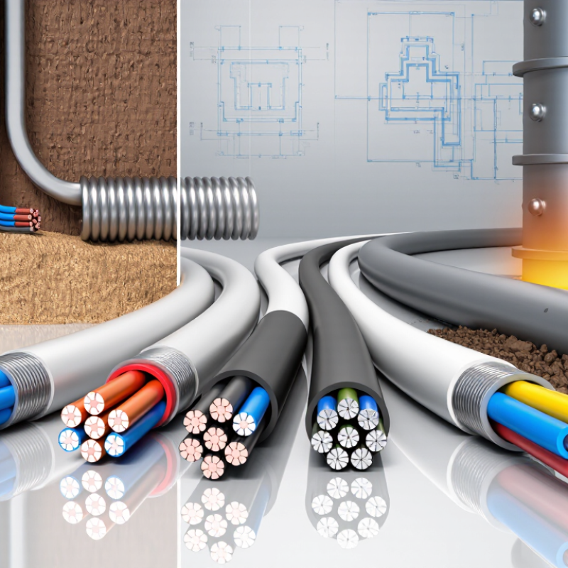
XLPE cable uses cross-linked polyethylene as its insulation. Heat and chemical treatment join polymer chains into a stable three-dimensional network. This structure limits molecular movement and reduces deformation under electrical stress. It also provides low dielectric loss, strong moisture resistance, and reliable performance in buried or industrial installations.
Under IEC 60502-1, common XLPE insulation systems allow a 90°C continuous conductor temperature and up to 250°C during short circuits. That thermal margin matters near substations, tunnels, and crowded cable trays. IEA’s Electricity Grids and Secure Energy Transitions report estimates that 80 million kilometers of grids must be added or refurbished globally by 2040. XLPE is likely to support much of this expansion, especially where compact, higher-capacity circuits are required.
The insulation still needs careful design. Water trees can develop in damp environments, while poor screening may intensify electric-field stress. CIGRE technical guidance emphasizes qualification testing, including thermal cycling, partial-discharge checks, and water-tree resistance for demanding cable systems. Choose the insulation level by voltage, installation depth, soil temperature, and expected load—not by conductor size alone. Field conditions can be less predictable. I would also question any selection based only on a catalog temperature rating. A cable that survives laboratory heat may perform differently beside wet soil, sharp bends, or overloaded joints.
XLPE cable types mainly differ by voltage, conductor arrangement, and installation environment. Low-voltage XLPE cables serve buildings, factories, and short distribution runs, commonly below 1 kV. Medium-voltage versions typically cover 1–33 kV and use semiconductive screens for controlled electric stress. High-voltage and extra-high-voltage cables require thicker insulation, metallic screens, and stricter testing under IEC 60840 and IEC 62067. Single-core designs suit high-current circuits, while multicore cables simplify compact distribution layouts. Armoured cables add mechanical protection underground or in industrial areas.
Demand is becoming less predictable. The IEA Electricity 2024 report expects global electricity demand to grow by more than 6% between 2023 and 2026. That increase supports new substations, renewable connections, and longer cable routes. Yet selecting XLPE only by voltage is risky. Check conductor material, allowable current, short-circuit rating, soil thermal resistivity, moisture exposure, and bending space. Copper reduces resistance, but aluminium can lower weight and installation cost. The cheaper choice is not always cheaper after jointing and maintenance.
For underground projects, water-blocked and armoured designs may improve resilience. For indoor switchgear, unarmoured cables can be easier to handle. CIGRE Technical Brochure 496 highlights the importance of complete cable-system testing, including joints and terminations, not just factory cable tests. This is often overlooked. A practical selection should compare calculated ampacity with field conditions, then confirm accessories, testing procedures, and service history with qualified engineers. Nakne?
XLPE cable types differ mainly in voltage rating, conductor design, shielding, and installation environment. Low-voltage multicore cables suit buildings and factory panels, while medium-voltage single-core cables reduce phase interaction and heat buildup. IEC 60502-1 covers power cables up to 3 kV, and IEC 60840 addresses systems above 30 kV to 150 kV. These limits matter during specification. A cable designed for a 33 kV feeder should not be treated like a 6 kV industrial cable.
Performance changes with construction. Copper offers strong conductivity, but aluminum can reduce weight and material cost. Armored cables resist crushing and accidental impact, making them practical for buried routes. Unarmored designs may work better in protected ducts. XLPE insulation normally supports a 90°C continuous conductor temperature, with short-circuit limits commonly reaching 250°C under applicable standards. Poor heat dissipation still reduces capacity. That detail is easy to miss.
Tips: Check the actual load profile, not only rated current. Compare soil thermal resistivity, burial depth, bending radius, and fault duration. IEC 62067 covers cables above 150 kV up to 500 kV, where testing and installation control become far stricter. The IEA’s Electricity Grids and Secure Energy Transitions report estimates annual grid investment must exceed 600 billion dollars by 2030. More projects will need reliable cable selection. Yet bigger capacity is not always better. Oversizing can increase cost, joint complexity, and installation difficulty. In practice, a shorter route with better thermal conditions may outperform a larger cable in poor soil.
| XLPE Cable Type | Typical Voltage Class | Common Construction | Key Performance Characteristics | Typical Applications | Main Selection Considerations |
|---|---|---|---|---|---|
| Low-Voltage XLPE Power Cable |
Up to 1 kV AC Common ratings include 0.6/1 kV |
|
|
Building services, industrial distribution, solar power systems, control panels, power plants and underground or tray installations. | Select conductor material, number of cores, sheath type, mechanical protection, installation method, voltage drop and permissible current. |
| Medium-Voltage XLPE Cable |
Above 1 kV to approximately 36 kV Common ratings include 6/10 kV, 8.7/15 kV and 12.7/22 kV |
|
|
Utility feeders, industrial substations, renewable-energy collector systems, transport infrastructure, commercial complexes and large motor supplies. | Verify insulation level, earthing method, screen cross-section, fault-current withstand, partial-discharge performance, thermal rating and termination compatibility. |
| High-Voltage XLPE Cable |
Commonly above 36 kV to approximately 150 kV Typical ratings include 64/110 kV and 76/132 kV |
|
|
Transmission substations, urban networks, power-generation connections, large industrial facilities and underground transmission routes. | Evaluate system voltage, insulation coordination, transient overvoltage, metallic-sheath bonding, induced voltage, route length, joints, terminations and testing requirements. |
| Extra-High-Voltage XLPE Cable |
Generally above 150 kV Project-specific ratings may include 220 kV, 275 kV and higher |
|
|
Major transmission corridors, dense urban areas, offshore or land-based grid connections and high-capacity interconnections. | Use a complete system design covering ampacity, thermal resistivity, sheath bonding, induced currents, mechanical pulling limits, joints, terminations and commissioning tests. |
| Single-Core XLPE Cable | Available across low-, medium- and high-voltage systems, depending on design | One insulated conductor per cable; cables may be installed in trefoil formation or flat formation. Magnetic armour requires special consideration for AC circuits. |
|
Substations, high-current feeders, generator connections, renewable-energy plants and transmission systems. | Check phase spacing, trefoil or flat formation, circulating-current losses, magnetic effects, cleating, short-circuit forces and sheath bonding. |
| Multicore XLPE Cable |
Mainly used in low- and medium-voltage systems Voltage rating depends on the cable construction |
Two-, three-, four- or five-core construction, with optional protective armour, filler, screen and outer sheath. |
|
Building distribution, industrial machinery, motor circuits, street lighting, control-power systems and compact switchboard connections. | Consider core identification, grouping derating, bending radius, installation space, neutral loading, armour requirements and termination size. |
| Armoured XLPE Cable | Commonly used in low- and medium-voltage installations; available for selected higher-voltage designs | XLPE-insulated cores with metallic armour, such as steel wire, steel tape or aluminium wire, beneath the outer sheath. |
|
Direct burial, industrial sites, outdoor trays, construction areas, mines and installations exposed to mechanical hazards. | Select armour material according to AC or DC use, mechanical risk, corrosion environment, fault-current requirements, burial conditions and termination method. |
| Unarmoured XLPE Cable | Commonly used in protected indoor, tray, conduit and duct installations across low- and medium-voltage systems | XLPE-insulated conductor or cores with bedding or separator layers and an outer sheath, without metallic armour. |
|
Indoor switchboards, cable trays, conduits, ducts, protected plant rooms and controlled industrial environments. | Confirm that the route provides adequate mechanical protection, fire performance, UV resistance, water resistance and support spacing. |
| Low-Smoke, Halogen-Free XLPE Cable | Mostly selected for low-voltage and certain medium-voltage applications | XLPE insulation combined with a low-smoke, halogen-free outer sheath and, where required, low-smoke bedding or fillers. |
|
Transport hubs, hospitals, tunnels, data centres, public buildings, high-rise structures and enclosed industrial facilities. | Check smoke, flame, fire-survival, toxicity, water-resistance, UV and mechanical test requirements specified for the project. |
| Water-Blocked XLPE Cable | Common in medium-, high- and extra-high-voltage systems, with voltage rating determined by the complete cable design | XLPE insulation with longitudinal or radial water-blocking materials, such as swellable tapes, powders or metallic moisture barriers. |
|
Underground utility networks, wet ducts, river crossings, coastal infrastructure, offshore connections and high-voltage routes. | Assess water-ingress risk, sheath testing, radial moisture barriers, joint sealing, installation environment and permissible pulling tension. |
Choosing an XLPE cable starts with the system, not the catalogue. Define the operating voltage, current, frequency, and expected load growth. A medium-voltage feeder may need a screened single-core cable, while a low-voltage installation may suit a multicore design. The wrong conductor size can create heat, voltage drop, and premature insulation aging.
Installation conditions matter just as much. Buried cables require attention to soil thermal resistivity, moisture, depth, and grouping. Cables in trays need suitable spacing and mechanical support. Check ambient temperature and solar exposure. In wet areas, select a sheath with appropriate moisture resistance. Where fire performance matters, review smoke, flame, and halogen requirements against local codes. Small details matter.
Termination compatibility is often overlooked. The cable screen, stress-control components, lugs, and accessories must match the insulation diameter and voltage class. Confirm short-circuit withstand, bending radius, pulling tension, and earthing arrangements. Use test records, manufacturer data, and applicable IEC or national standards before approval. Field experience shows that a cable can look ideal on paper but fail during installation because the bend radius was underestimated. I have seen this happen. Cost also deserves a wider view; cheaper cable may require larger trenches, stronger supports, or earlier replacement. No selection is perfect. Recheck assumptions with the installer, protection engineer, and maintenance team before ordering.
Verifying an XLPE cable starts before it reaches the trench. Request the manufacturer’s type-test, routine-test, and material traceability records. IEC 60502-1 and IEC 60840 define key requirements for construction, electrical testing, and voltage classes. Check conductor resistance, insulation dimensions, partial discharge results, and metallic sheath continuity. Compare serial numbers with the delivery documents. A polished certificate is not proof of every drum.
Pay special attention to accessories. A CIGRE industry survey indicates that accessories can cause roughly 70% of reported XLPE cable failures. Inspect joints and terminations for clean insulation cuts, correct stress-control components, and measured torque values. During installation, record pulling tension, cable temperature, bend radius, and roller spacing. Keep the cable ends sealed. Water enters quietly. The IEA’s Electricity Grids and Secure Energy Transitions report estimates that over 80 million kilometres of grids must be added or refurbished globally by 2040, increasing pressure on installation quality.
After laying, perform sheath integrity testing and an appropriate AC or VLF withstand test under IEEE 400.2 guidance. Use calibrated instruments, trained technicians, and signed test records. Thermal backfill matters too; poor compaction can create hot spots around the cable. I have seen complete paperwork hide a rushed termination. That is an uncomfortable limitation. Independent inspection and photographic evidence still deserve more attention.
How to use this chart: XLPE-insulated power cables commonly use a 90°C maximum continuous conductor temperature, while a short-circuit conductor temperature of up to 250°C is widely specified for short durations under applicable IEC cable standards. A temporary overload reference of 105°C may be permitted only when the project standard and installation conditions allow it. Final cable selection must verify rated voltage, conductor size, current-carrying capacity, voltage drop, short-circuit withstand, bending radius, burial or tray conditions, sheath bonding, and test certificates in accordance with the applicable IEC requirements.
Low-voltage cables usually serve buildings and factories below 1 kV. Medium-voltage cables often cover 1–33 kV. High-voltage cables need thicker insulation and stricter testing.
Single-core cables suit high-current circuits. Multicore cables make compact distribution layouts easier. The choice depends on current, space, installation method, and maintenance access.
Armoured cables add mechanical protection underground or in industrial areas. They can resist physical damage from soil, tools, or nearby construction activity. Indoor switchgear may need lighter, unarmoured designs.
Copper usually reduces electrical resistance. Aluminium can reduce cable weight and installation cost. The cheaper drum may cost more after jointing, transport, and maintenance.
Check allowable current, short-circuit rating, soil thermal resistivity, moisture exposure, and bending space. Also review conductor material and installation length. Voltage alone is not enough.
Request type-test, routine-test, and material traceability records. Check conductor resistance, insulation dimensions, partial discharge results, and metallic sheath continuity. Match drum serial numbers with delivery documents.
Accessories can cause many cable failures. Inspect clean insulation cuts, stress-control parts, and torque values. A cable may look excellent while one rushed termination remains hidden.
Record pulling tension, cable temperature, bend radius, and roller spacing. Keep cable ends sealed during storage. Water enters quietly.
Perform sheath integrity testing and a suitable AC or very-low-frequency withstand test. Use calibrated instruments and trained technicians. Record every result with signatures and photographs.
No. Complete paperwork can still hide poor workmanship. Inspect thermal backfill, because weak compaction may create hot spots around the cable. Independent inspection deserves more attention.
Xlpe Cable is a power cable that uses cross-linked polyethylene insulation to provide strong electrical resistance, heat stability, and reliable protection against moisture and mechanical stress. Its insulation structure allows the cable to operate safely under demanding temperature and load conditions while reducing the risk of aging and electrical failure. Common types include single-core, multicore, low-voltage, medium-voltage, and high-voltage cables, each designed for different transmission, distribution, industrial, or infrastructure applications.
Choosing the right Xlpe Cable requires careful consideration of voltage level, conductor material, current capacity, installation environment, flexibility, temperature range, grounding needs, and expected service life. Buyers should also review conductor size, insulation thickness, shielding, outer sheath protection, and compliance with applicable electrical standards. Before installation, verify product test reports, markings, dimensional accuracy, and quality documentation. Correct bending radius, jointing methods, termination procedures, and testing practices are equally important for achieving safe, efficient, and long-lasting cable performance.

Lucky Pioneer